Homepage    
  Site Map
  Contact us
  Directions The reference for phased array probes  
   

Search Imasonic
Medical
Company
  Performance & Innovation
Your project
Papers
Products
Immersion
Phased Array


>>
Principle
Virtual examples
Design notes for phased array
Main Imasonic features
Imasonic performance
Linear arrays (immersion)
Linear arrays (Contact)
TRL phased array
Curved and circular arrays
Annular arrays
Matrix arrays
T.O.F.D.
Special
NDT Applications
Nuclear & power generation
Aeronautics
Metal Industry
Petrochemical
Transportation
Measurement
Application examples


Design notes for linear phased array probes

Grating lobes

When using a phased array transducer, delay laws are applied to each channel to generate a beam with a given refraction angle and focal distance. The ultrasonic beam is generated by the constructive interference of each transducer element’s contribution in the desired direction. See phased array principle here >>

In some cases, this interference can also be constructive in other directions. These lobes of energy emitted outside the electronically driven direction are called grating lobes.
These energy lobes can interact with the part to be inspected in the same way as the main beam, and thus generate echoes causing interference to the inspection. Therefore they have to be avoided as much as possible.

The angle of the position of grating lobes in relation to the main beam is given by the following formula

sin qk = k . l / p - sin q

q = refracted angle of the main beam
qk = refracted angle of the grating lobe k (k: integer)
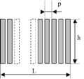
P = inter-element pitch (p) of the linear transducer
l = wavelength in the medium under consideration

Note: this formula is only valid in the case of electronic deflection (linear delay law) . In case of electronic focusing, the angular deviation between the main beam and the grating lobes is reduced.

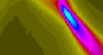
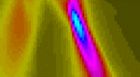
Case 1 (see below) : p < l/2, no grating lobe Case 2 : p > l, appearance of a grating lobe (on the left), even with lower refraction angle of the main beam

From the above formula, the following general rule can be obtained :
- If p < l/2, then no grating lobe is generated whatever the angle of the main beam.
- If p > l, then there is always at least one grating lobe generated whatever the angle of the main beam.
- Between these two values, the grating lobes appear progressively according to the angle of the main beam.

Lateral resolution along the plane of incidence

The following formula allows a good approximation to be made of the lateral resolution, and allows the correlation between the active aperture and the lateral resolution to be rapidly checked

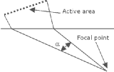
W = 0.44.l / sin ( a / 2)

W= focal spot or beam width (at –6dB in emission reception)
l = wave length in the medium under consideration
a = angle beneath which the active area is seen from the focal point

Note: This formula is valid when the hypothesis of electronic focusing at the focal point under consideration is made

Number of elements

Knowing the inter-element spacing required to avoid grating lobes, and the width of the active aperture, the number of elements necessary can be rapidly deduced.
If the appropriate number of electronic channels is not available for technical or economic reasons, the best possible compromise must be found, by readjusting the inter-element spacing, the frequency, and/or the active aperture (and thus the lateral resolution)

Note: Some linear array sensors are also used for electronic scanning. In this case, the beam is generated by only some of the elements. To calculate the lateral resolution, only the size of the active area is to be taken into account.

  Top of this page
© 2002 Imasonic S.A.